
1. Johdanto
The UNI-T UT526 is a multifunction electrical installation tester designed for comprehensive electrical system analysis. It accurately measures insulation resistance, RCD (Residual Current Device) status, low resistance continuity, and AC/DC voltage. This device is suitable for testing power distribution systems, lightning protection systems, and wiring systems to ensure safe operation and compliance with electrical standards.

Kuva 1: Etuosa view of the UNI-T UT526 Multifunction Electrical Installation Tester.
2. Turvallisuustiedot
Before operating the UT526, read and understand all safety warnings and operating instructions. Failure to follow these instructions may result in electric shock, fire, or serious injury. Keep this manual for future reference.
- Varmista aina ennen käyttöä, että laite on hyvässä toimintakunnossa.
- Älä käytä testeriä, jos se näyttää vaurioituneelta tai jos mittausjohdot ovat vaurioituneet.
- Varmista testerin oikea toiminta tunnetulla tilavuusprosentillatage lähde ennen ja jälkeen käytön.
- Noudata kaikkia paikallisia ja kansallisia turvallisuusmääräyksiä.
- Käytä asianmukaisia henkilönsuojaimia, mukaan lukien suojalasit ja eristetyt käsineet.
- Avoid working alone when performing electrical tests.
- Älä ylitä minkään toiminnon enimmäistulotehoa.
- Ensure the circuit under test is de-energized and locked out before making connections for resistance or continuity measurements.
3. Pakkauksen sisältö
Carefully unpack the box and ensure all items listed below are present and undamaged. If any item is missing or damaged, contact your supplier immediately.
- 1 x UT526 Earth Resistance Tester
- 1 x Test Lead Set
- 1 x Alligator Clip Set
- 1 x englanninkielinen käyttöohje
- 1 x olkahihna
- 1 x kantolaukku
- 1 x värilaatikko
Note: Batteries are not included and must be purchased separately (1.5V AA batteries x 6).
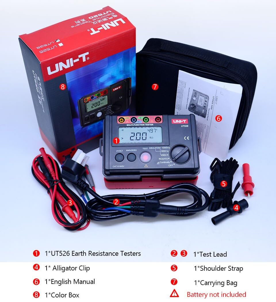
Figure 2: Included components of the UT526 package.
4. Tuotteen ominaisuudet
The UNI-T UT526 offers a range of features for reliable electrical installation testing:
- Näytön määrä: 10000 for precise readings.
- Manuaalinen alue: Allows for specific range selection.
- Phase Switch (RCD): Supports 0° and 180° phase testing.
- Alhaisen akun ilmoitus: Hälyttää, kun paristot on vaihdettava.
- Auto AC/DC Voltage Tunnistus: Simplifies voltage mittaukset.
- Red Warning Lights: Visual alert for hazardous conditions.
- Sertifikaatit: CE, UKCA compliant.
5. Asennus
Before first use, install the batteries and prepare the test leads.
5.1 Akun asennus
- Paikanna laitteen takaosasta paristolokero.
- Avaa paristokotelon kansi ruuvitaltalla.
- Insert 6 x 1.5V AA batteries, observing the correct polarity.
- Aseta akun kansi takaisin paikalleen ja kiinnitä se ruuvilla.
5.2 Mittausjohtojen kytkeminen
Connect the test leads to the appropriate input terminals on the UT526. The terminals are color-coded and labeled for clarity (e.g., LINE, N, E, L).
6. Käyttöohjeet
The UT526 offers various measurement functions. Select the desired function using the rotary switch.
6.1 Measuring Insulation Resistance
This function measures the insulation resistance of electrical circuits and equipment.
- Turn the rotary switch to one of the insulation test voltage settings: 100V, 250V, 500V, or 1000V.
- Insert test leads into the input terminals (Red to LINE, Black to N) and connect them to the circuit under test. High voltage lähetetään LINE-liittimestä.
- For continuous measurement, press the TESTATA button. The tester will self-lock, output the test voltage, and emit a warning light simultaneously.
- Once the measurement is finished, press TESTATA again to unlock and stop the continuous measurement.
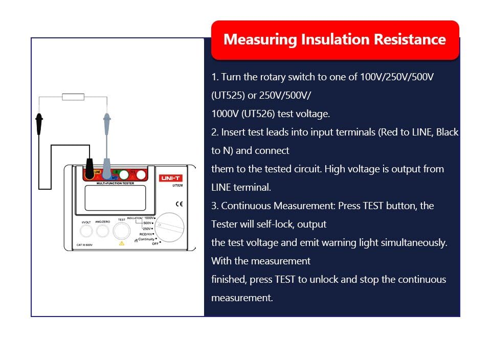
Figure 3: Setup for measuring insulation resistance.
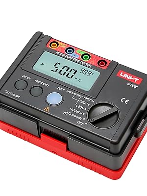
Figure 4: UT526 performing an insulation resistance test with warning light activated.
6.2 RCD-testi (vikavirtasuoja)
The RCD test function verifies the proper operation of Residual Current Devices, ensuring they trip within specified parameters.
- Turn the rotary switch to the RCD function.
- Connect the test leads to the appropriate terminals of the RCD or circuit.
- Select the desired test current and phase (0° or 180°) using the function buttons.
- Initiate the test. The device will measure the trip time and display the result.
Video 1: Demonstration of the RCD test function using the UNI-T UT526. This video shows the connection and operation of the RCD test, illustrating how the device measures the trip time of a residual current device.

Figure 5: UT526 connected for an RCD test.
6.3 Low Resistance Continuity Measurement
This function checks for continuity in circuits and measures low resistance values.
- Turn the rotary switch to the Continuity function.
- Connect the test leads across the component or circuit to be tested.
- The display will show the resistance value. An audible beep indicates continuity (typically below a certain resistance threshold).

Figure 6: UT526 performing a low resistance continuity test on a motor.
6.4 AC/DC Voitage Mittaus
The UT526 can measure both AC and DC voltages.
- Turn the rotary switch to the V (Voltage) function. The device will automatically identify AC or DC voltage.
- Connect the test leads in parallel with the circuit or component where voltage on mitattava.
- Näytössä näkyy mitattu tilavuustage arvo.
6.5 Ground Resistance Measurement
While the UT526 is primarily a multifunction electrical installation tester, it also supports ground resistance measurements.
- Turn the rotary switch to the appropriate ground resistance setting (if available, or use continuity for basic checks).
- Connect the test leads according to the specific ground resistance testing method (e.g., 3-pole or 4-pole method, if supported by the model).
- Initiate the measurement and read the ground resistance value from the display.

Figure 7: UT526 connected for ground resistance testing.
7. Huolto
Proper maintenance ensures the longevity and accuracy of your UT526 tester.
- Puhdistus: Pyyhi laite mainoksellaamp cloth and mild detergent. Do not use abrasive cleaners or solvents. Ensure the device is dry before storage.
- Akun vaihto: Vaihda paristot välittömästi, kun heikon pariston varoitusvalo tulee näkyviin. Poista paristot, jos laitetta ei käytetä pitkään aikaan vuotojen estämiseksi.
- Varastointi: Store the tester in a cool, dry place, away from direct sunlight and extreme temperatures. Use the provided carrying bag for protection.
- Kalibrointi: For professional use, periodic calibration by an authorized service center is recommended to maintain measurement accuracy.
8. Vianmääritys
If you encounter issues with your UT526, refer to the following common problems and solutions:
| Ongelma | Mahdollinen syy | Ratkaisu |
|---|---|---|
| Laite ei käynnisty | Tyhjät tai väärin asennetut paristot | Vaihda paristot ja varmista oikea napaisuus. |
| Epätarkkoja lukemia | Poor test lead connection, out of calibration, environmental interference | Ensure secure connections. Check against a known source. Consider professional calibration. |
| RCD test fails to trip | Faulty RCD, incorrect test parameters, wiring issue | Verify RCD functionality independently. Check test current and phase settings. Inspect circuit wiring. |
| Näytössä näkyy "OL" (ylikuormitus) | Measurement exceeds selected range or device capability | Select a higher range or ensure the measurement is within the device's specifications. |
9. Tekniset tiedot
Detailed technical specifications for the UNI-T UT526 Multifunction Electrical Installation Tester are provided below.

Figure 8: Comprehensive specifications for the UT526.
| Erittely | Arvo |
|---|---|
| Merkki | UNI-T |
| Malli | HY-UT526 |
| Virtalähde | Battery Powered (6 x 1.5V AA) |
| Tuotteen paino | 0.6 kg |
| Tuotteen mitat | 6.5 x 4.33 x 4.72 tuumaa |
| Erittely Met | CE, ISO 9001, RoHS, UKCA |
| Näytön määrä | 10000 |
| Eristysresistanssitesti Voitages | 100V, 250V, 500V, 1000V |
| RCD Phase Switch | 0° ja 180° |
| Alhaisen akun ilmoitus | Kyllä |
| Auto AC/DC Voltage-tunnistus | Kyllä |
| Punaiset varoitusvalot | Kyllä |
10. Takuu
The UNI-T UT526 Multifunction Electrical Installation Tester comes with a 1 vuoden takuu ostopäivästä lukien. Tämä takuu kattaa materiaali- ja valmistusvirheet normaalissa käytössä. Se ei kata väärinkäytöstä, onnettomuudesta, luvattomasta muutoksesta tai laiminlyönnistä aiheutuneita vahinkoja. Säilytä ostokuitti takuuvaatimuksia varten.
11. Tukea
For technical assistance, troubleshooting beyond this manual, or warranty inquiries, please contact UNI-T customer support. Refer to the official UNI-T webKatso ajantasaisimmat yhteystiedot verkkosivustoltasi tai tuotepakkauksesta.
UNI-T:n virkamies Websivusto: www.uni-trend.com