
1. Johdanto
The EC Buying ADS1256 module is a high-precision 24-bit analog-to-digital converter designed for accurate data acquisition. It features an on-board ADS1256IDB ADC chip and an ADR03 2.5V power reference chip, ensuring stable and reliable measurements. This module is suitable for various applications requiring precise analog voltage measurement and conversion.
2. Tärkeimmät ominaisuudet
- On-board high precision ADS1256IDB ADC chip.
- Onboard ADR03 2.5V power reference chip.
- Data output rate up to 30ksps.
- Low nonlinearity of 0.0010%.
- Configurable as 8 single-ended inputs or 4 differential inputs.
- Suitable for measuring analog voltage within 3V.
- Module operating voltage: 5V.
- Connectivity: SPI interface.
3. Moduuli ohiview
The ADS1256 module is a compact board with clearly labeled pins for easy integration. Below are images illustrating the module's components and dimensions.

Kuva 3.1: Yläosa view of the ADS1256 module, highlighting the ADS1256IDB chip and other surface-mount components.

Figure 3.2: ADS1256 module dimensions, measuring approximately 60mm in length and 35mm in width.
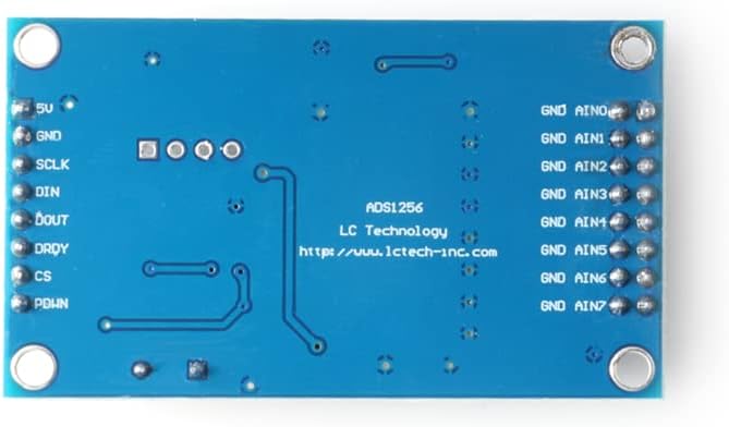
Kuva 3.3: Pohja view of the ADS1256 module, displaying pinout labels for power (5V, GND), SPI communication (SCLK, DIN, DOUT, DRDY, CS, PDWN), and analog inputs (AIN0-AIN7).
4. Asennusohjeet
Follow these steps to set up your ADS1256 module:
- Virtalähde: Connect a stable 5V DC power supply to the '5V' and 'GND' pins of the module. Ensure the power supply can provide sufficient current for the module's operation.
- SPI Connection: Connect the module to your microcontroller (e.g., STC15W, STM32, STC89C52) using the SPI interface. The required pins are:
- SCLK: Sarjakellon syöttö
- DIN: Data Input (MOSI)
- DOUT: Data Output (MISO)
- DRDY: Data Ready Output
- CS: Chip Select Input
- PDWN: Power Down Input
- Analoginen tulo: Connect your analog voltage source to the 'AIN0' through 'AIN7' pins. The module supports 8 single-ended inputs or 4 differential inputs. For differential measurements, connect the positive input to AINx and the negative input to AIN(x+1) (e.g., AIN0 and AIN1 for one differential pair).
- Ground Reference: Ensure all analog input grounds are connected to the module's 'GND' pin for accurate readings.
5. Käyttöohjeet
To operate the ADS1256 module, you will need to program your microcontroller to communicate via SPI and configure the ADC.
- Alustus: After power-up, initialize the ADS1256 by sending appropriate commands via SPI. This includes setting the data rate, gain, and input multiplexer configuration (single-ended or differential). Refer to the ADS1256 datasheet for detailed register configurations.
- Syöttöasetukset: Decide whether to use single-ended or differential inputs. For single-ended, each AINx pin measures voltage relative to ground. For differential, the module measures the voltage difference between two AIN pins. The module can measure analog voltages within a 3V range.
- Tiedonhankinta: To read data, assert the CS pin low, send the read command, and then read the 24-bit digital output from the DOUT pin. The DRDY pin will go low when new conversion data is ready.
- Jatkuva mittaus: For continuous measurements, repeatedly send the read command and process the data. The module's data output rate can reach 30ksps, allowing for high-speed acquisition.
6. Huolto
Proper maintenance ensures the longevity and performance of your ADS1256 module:
- Käsittely: Handle the module with care, avoiding static discharge. Use anti-static precautions when working with electronic components.
- Puhdistus: Keep the module clean and free from dust and debris. Use a soft, dry brush or compressed air for cleaning. Avoid using liquids or solvents.
- Varastointi: Store the module in a dry, cool environment, away from direct sunlight and extreme temperatures. If not in use for extended periods, store it in an anti-static bag.
- Liitännät: Tarkista säännöllisesti kaikki liitokset varmistaaksesi, että ne ovat tukevasti kiinni ja että niissä ei ole korroosiota.
7. Vianmääritys
If you encounter issues with your ADS1256 module, consider the following troubleshooting steps:
- Ei virtaa: Verify that the 5V power supply is correctly connected and providing the specified voltage. Check for loose wires or incorrect polarity.
- Väärät lukemat:
- Ensure analog input voltages are within the 3V operating range.
- Check all SPI connections for continuity and correct pin assignments (SCLK, DIN, DOUT, DRDY, CS, PDWN).
- Verify your microcontroller's SPI communication code and ADS1256 register configurations.
- Confirm that the analog input ground is properly connected to the module's GND.
- Check the reference voltage (ADR03 2.5V) for stability.
- Ei datalähtöä:
- Ensure the CS pin is correctly toggled during SPI communication.
- Check the DRDY pin status; it should go low when data is ready. If it remains high, the ADC might not be converting.
- Verify the SPI clock speed is compatible with both the microcontroller and the ADS1256 module.
- Moduuli ei vastaa: Try power cycling the module and the microcontroller. Recheck all wiring.
8. Tekniset tiedot
| Ominaisuus | Yksityiskohta |
|---|---|
| Merkki | EY-osto |
| Mallin nimi | ADS1256 8-channel 24-bit ADC Module |
| Yhteystekniikka | SPI |
| Käyttöjärjestelmän yhteensopivuus | FreeRTOS (example) |
| CPU:n valmistaja | Texas Instruments (for ADS1256 chip) |
| Prosessorin merkki | Texas Instruments (for ADS1256 chip) |
| Yhteensopivat laitteet | STC15W microcontroller, STM32 microcontroller, STC89C52 microcontroller |
| Prosessorin määrä | 1 (referring to the ADC chip) |
| Valmistaja | EY-osto |
| ASIN | B0BMPKQKZP |
9. Takuu ja tuki
For warranty information or technical support regarding your EC Buying ADS1256 module, please refer to the product's purchase documentation or contact EC Buying directly through their official channels. Keep your proof of purchase for any warranty claims.
Voit vierailla EC Buying Store on Amazon lisätietoja ja yhteydenottovaihtoehtoja varten.