
1. Johdanto
Thank you for choosing the Voltcraft VC-11 Digital Multimeter. This portable, Category III, 250V multimeter with a 2000-count display is designed for accurate electrical measurements in various applications. This manual provides essential information for safe operation, proper use, and maintenance of your device. Please read it thoroughly before use and keep it for future reference.
2. Turvallisuustiedot
WARNING: Electrical shock hazard. Improper use of this meter can cause damage, shock, injury, or death. Read and understand this manual before operating the meter.
- Always ensure the meter is in good working condition and the test leads are not damaged.
- Älä käytä enempää kuin nimellistilavuustage, kuten mittariin on merkitty, liittimien väliin tai minkä tahansa liittimen ja maan väliin.
- Ole erittäin varovainen, kun työskentelet voltages above 25V AC RMS or 35V DC. These voltagse aiheuttaa sähköiskuvaaran.
- Irrota aina mittausjohdot piiristä ennen toimintojen tai mittausalueiden vaihtamista.
- Älä käytä mittaria paristokotelon kannen ollessa irrotettuna tai löysällä.
- Adhere to local and national safety codes. Use personal protective equipment (PPE) such as approved safety glasses and electrically insulated gloves.
3. Tuote ohiview
The Voltcraft VC-11 is a compact digital multimeter featuring a clear LCD display, a rotary function switch, and input jacks for test leads. It is designed for measuring DC/AC voltage, DC current, resistance, and includes diode and continuity test functions.
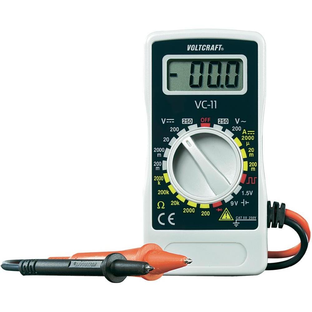
Kuva 1: Etuosa view of the Voltcraft VC-11 Digital Multimeter with test leads connected. This image shows the LCD display, rotary switch, and input terminals.

Kuva 2: Kulmassa view of the Voltcraft VC-11 Digital Multimeter, highlighting the compact design and the CE marking.

Figure 3: The Voltcraft VC-11 Digital Multimeter shown with its test leads detached, illustrating the input ports.
3.1 Komponentit
- LCD-näyttö: Näyttää mittauslukemat, yksiköt ja toimintojen ilmaisimet.
- Kiertokytkin: Käytetään mittaustoimintojen ja -alueiden valitsemiseen.
- Tuloliittimet: Ports for connecting the test leads (COM, VΩmA).
- Testijohdot: Red and black leads for connecting to the circuit under test.
4. Asennus
4.1 Akun asennus
The Voltcraft VC-11 requires a 9V battery for operation (not included). To install or replace the battery:
- Varmista, että yleismittari on sammutettu ja irrota kaikki mittausjohdot.
- Paikanna paristolokeron kansi mittarin takaa.
- Irrota akun kannen kiinnittävä ruuvi ruuvimeisselillä.
- Poista kansi varovasti.
- Kytke uusi 9 V:n paristo paristoliittimeen ja varmista, että napaisuus on oikein.
- Aseta akku lokeroon ja sulje kansi ruuvilla.
4.2 Mittausjohtojen kytkeminen
Always connect the black test lead to the 'COM' (common) jack. Connect the red test lead to the appropriate input jack based on the desired measurement:
- Osalle Voltage (V), Resistance (Ω), Diode, and Continuity measurements, connect the red lead to the 'VΩmA' jack.
- For Current (A) measurements, connect the red lead to the 'VΩmA' jack (for mA range).
5. Käyttöohjeet
Ennen mittausten suorittamista varmista, että mittausjohdot on kytketty oikein ja että kiertokytkin on asetettu haluttuun toimintoon ja mittausalueeseen.
5.1 Mittaus DC Voltage (V=)
- Aseta kiertokytkin haluttuun tasavirta-asentoon.tage (V=) range (e.g., 200mV, 2V, 20V, 200V, 250V). If the voltagJos e on tuntematon, aloita suurimmasta arvosta ja pienennä tarvittaessa.
- Kytke musta mittausjohto 'COM'-liittimeen ja punainen mittausjohto 'VΩmA'-liittimeen.
- Kytke mittausanturit rinnan mitattavan komponentin tai piirin kanssa.
- Lue voltage -arvo nestekidenäytössä.
5.2 AC:n mittaus Voltage (V~)
- Aseta kiertokytkin haluttuun AC Vol -asentoontage (V~) -alue (esim. 200 V, 250 V).
- Kytke musta mittausjohto 'COM'-liittimeen ja punainen mittausjohto 'VΩmA'-liittimeen.
- Kytke mittausanturit rinnan vaihtovirtalähteen tai -komponentin yli.
- Lue voltage -arvo nestekidenäytössä.
5.3 Tasavirran (A=) mittaaminen
- Set the rotary switch to the desired DC Current (A=) range (e.g., 2000µA, 20mA, 200mA).
- Kytke musta mittausjohto 'COM'-liittimeen ja punainen mittausjohto 'VΩmA'-liittimeen.
- VAROITUS: To measure current, the meter must be connected in series with the circuit. Break the circuit and insert the meter.
- Kytke mittausanturit sarjaan piiriin.
- Lue nykyinen arvo LCD-näytöltä.
5.4 Resistanssin (Ω) mittaaminen
- Varmista, että virtapiiri on jännitteetön ennen resistanssin mittaamista.
- Set the rotary switch to the desired Resistance (Ω) range (e.g., 200Ω, 2kΩ, 20kΩ, 200kΩ, 2000kΩ).
- Kytke musta mittausjohto 'COM'-liittimeen ja punainen mittausjohto 'VΩmA'-liittimeen.
- Kytke mittausjohdot mitattavan komponentin päälle.
- Lue vastusarvo LCD-näytöltä.
5.5 Dioditesti
- Varmista, että virtapiiri on jännitteetön.
- Set the rotary switch to the Diode symbol (usually next to resistance).
- Kytke musta mittausjohto 'COM'-liittimeen ja punainen mittausjohto 'VΩmA'-liittimeen.
- Kytke punainen anturi diodin anodiin ja musta anturi diodin katodiin. Näytössä näkyy eteenpäin suuntautuva jännite.tage pudota.
- Reverse the probes. The display should show 'OL' (Overload) for a good diode.
5.6 Jatkuvuustesti
- Varmista, että virtapiiri on jännitteetön.
- Set the rotary switch to the Continuity symbol (usually next to diode/resistance).
- Kytke musta mittausjohto 'COM'-liittimeen ja punainen mittausjohto 'VΩmA'-liittimeen.
- Kytke mittausjohdot piiriin tai komponenttiin.
- If the resistance is below a certain threshold (typically 30-50Ω), the meter will emit an audible beep, indicating continuity.
6. Huolto
6.1 Puhdistus
Pyyhi mittari mainoksellaamp liinalla ja miedolla pesuaineella. Älä käytä hankaavia aineita tai liuottimia. Varmista, että mittari on täysin kuiva ennen käyttöä.
6.2 Pariston vaihto
When the battery symbol appears on the LCD display, the 9V battery needs to be replaced. Refer to section 4.1 for battery installation instructions.
7. Vianmääritys
| Ongelma | Mahdollinen syy | Ratkaisu |
|---|---|---|
| Ei näyttöä tai himmeä näyttö | Tyhjä tai vähissä akku | Vaihda 9 V: n paristo. |
| Väärät lukemat | Incorrect function/range selected Poor test lead connection Damaged test leads | Select the correct function and range. Ensure test leads are firmly connected. Inspect and replace damaged test leads. |
| Näytössä näkyy "OL" (ylikuormitus) | Mittaus ylittää valitun alueen Open circuit (for resistance/current) | Select a higher range. Check for breaks in the circuit. |
8. Tekniset tiedot
- Merkki: VOLTCRAFT
- Mallinumero: VC11
- Valmistaja: VOLTCRAFT
- Tuotteen paino: Approximately 9.07 g (without packaging)
- Paketin mitat: 14.8 x 8 x 3.6 cm
- Luokkaluokitus: CATIII 250V
- Näyttö: 2000 laskentaa
- Virtalähde: 9 V:n paristo (ei sisälly toimitukseen)
9. Takuutiedot
This product is covered by a standard manufacturer's warranty. Please refer to the warranty card included with your purchase or contact your retailer for specific terms and conditions. The warranty typically covers defects in materials and workmanship under normal use.
10. Asiakastuki
For technical assistance, troubleshooting, or service inquiries, please contact Voltcraft customer support or your local distributor. Contact information can usually be found on the manufacturer's websivustolla tai tuotepakkauksessa.